
Soldering Flip-Pins
Note: Please check the notes at the bottom of the page if you are using Flip-Pins for the first time or you are doing rework.
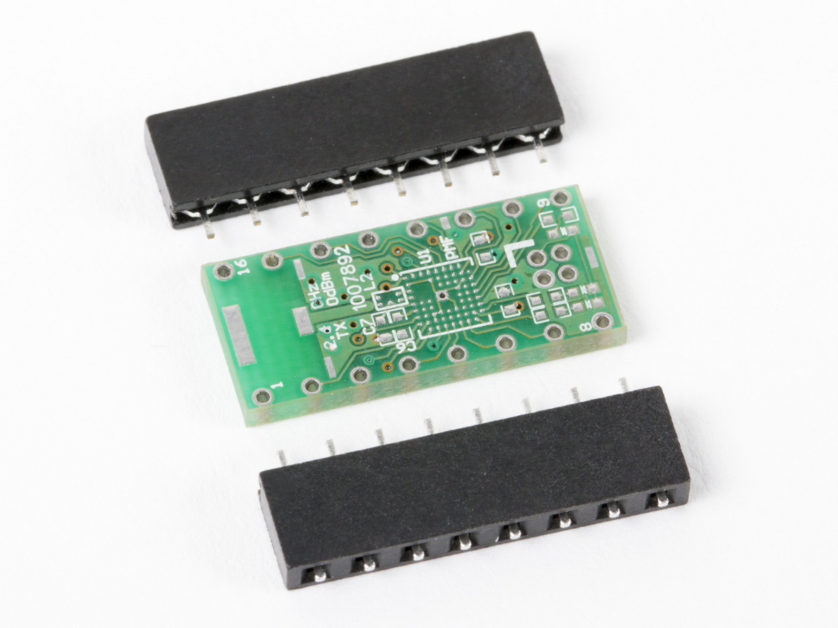
| Parts to be assembled. For clarity, all pictures are shown without
other components. Typically you would mount all other components first, before soldering in Flip-Pins. Photo Credit for all picture: Windell Oskay |
 |
| Insert the soldertail end of the Flip-Pin into the appropriate holes on your PCB | 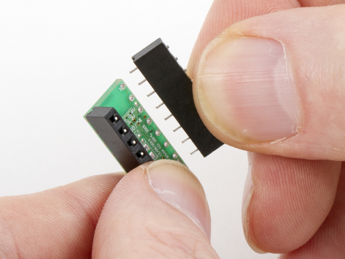 |
| Place your board with the Flip-Pins on a flat surface Note: When soldering, if you add too much solder, it will wick down the pin and wont be obvious until the plastic aligner is removed. |
 |
| Solder 1 pin, at the end, of each Flip-Pin strip(s). Note: If this is your first time soldering Flip-Pins, you might want to practice on a spare prototype PCB to get a feel for how much solder is the right amount. |
 |
| After soldering the end pins, your board should look like this. | 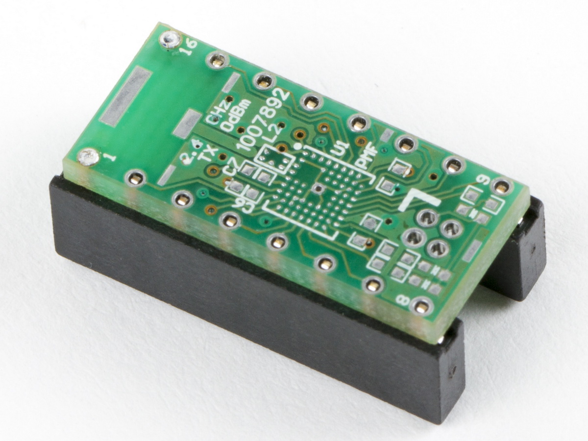 |
| Take the assembly, and check that the plastic aligner(s) is at right-angle to the PCB |  |
| Check that the plastic aligner(s) is flush to the PCB | 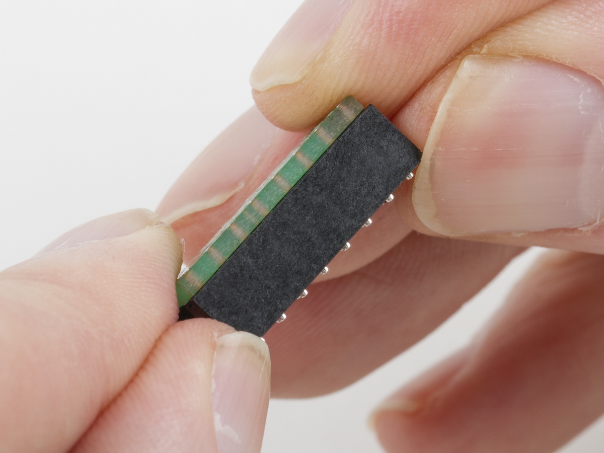 |
| Solder the remaining pins | 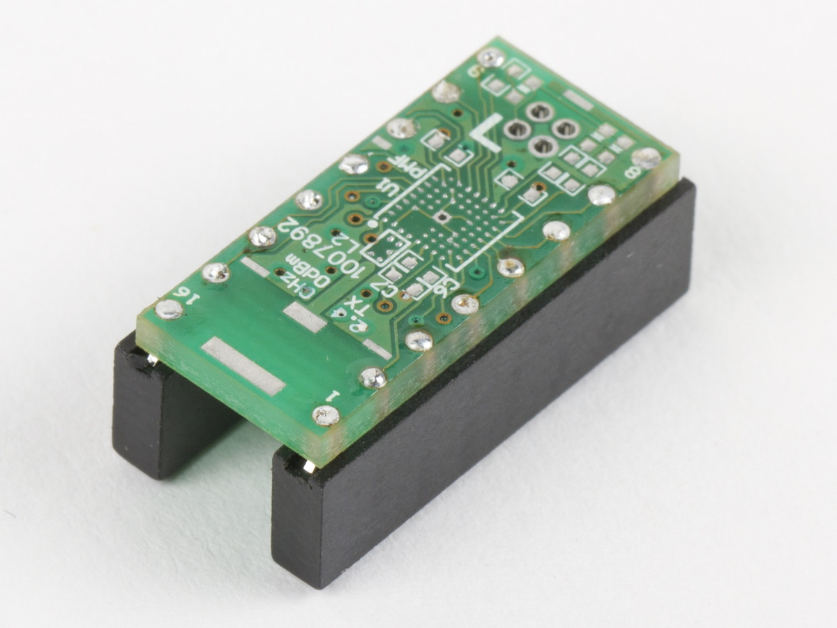 |
| Remove the plastic aligner(s) by pulling it off, being careful not to bend the pins | 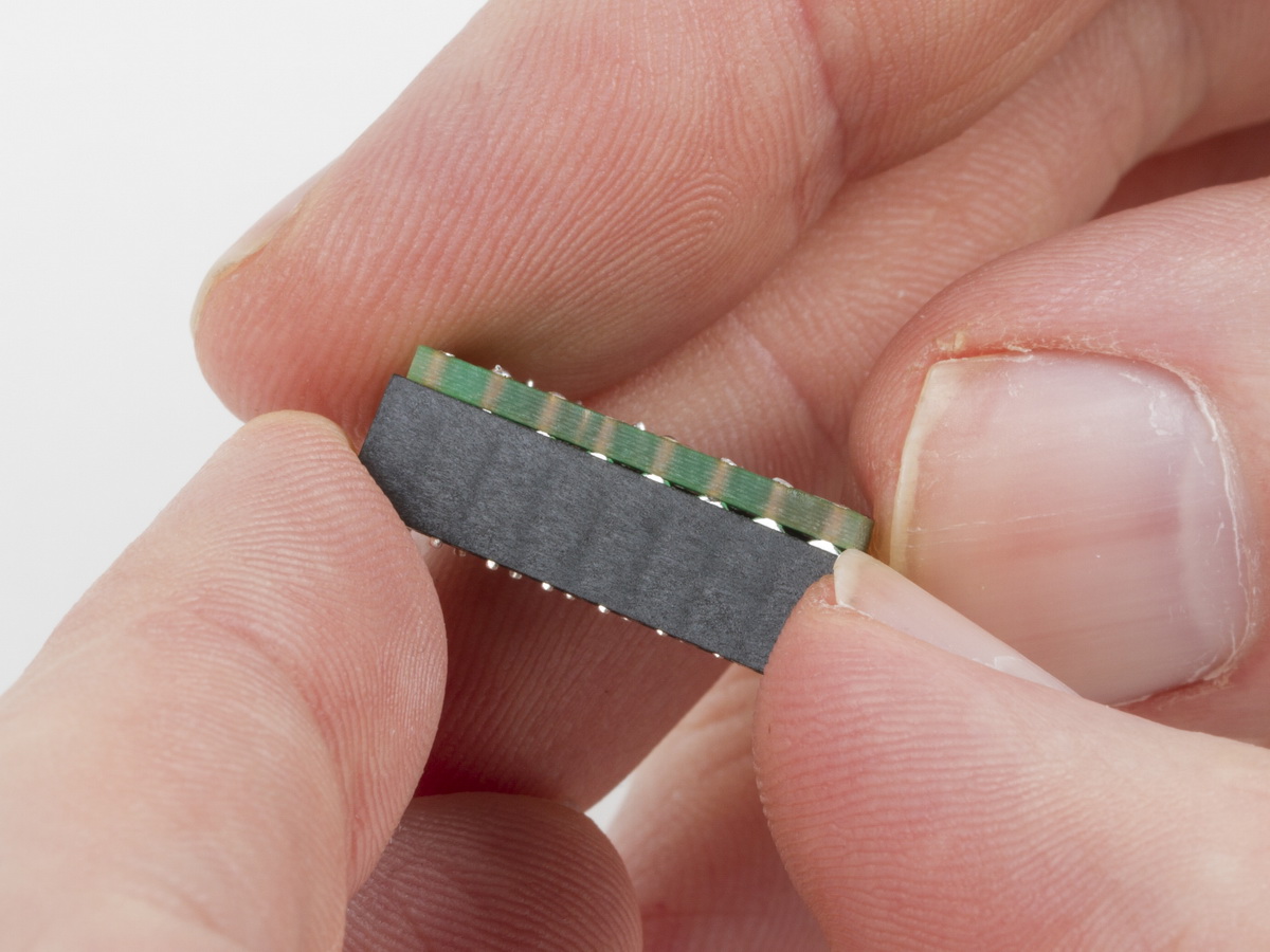 |
| With the plastic aligner removed, you may optionally inspect the pin side of the PCB and see if there is sufficient solder to fill the hole in the PCB. If you want to add more solder, put the aligner back on the pins, and add more solder from the top side. If there is too much solder, learn to use less, next time. |  |
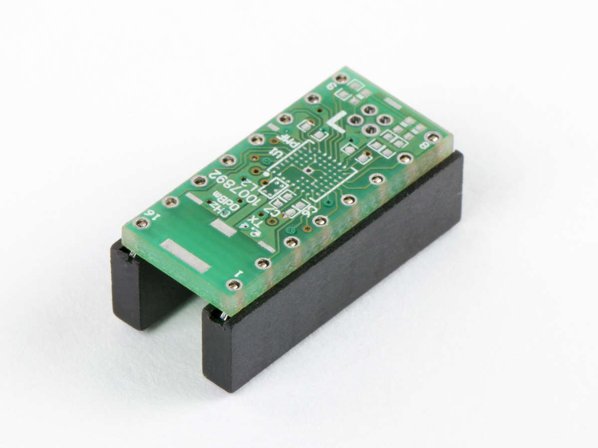
| The finished assembly after all aligner(s) have been removed. | 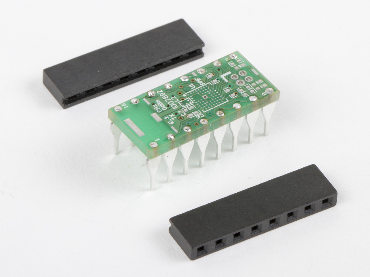 |
| Another view of the finished assembly | 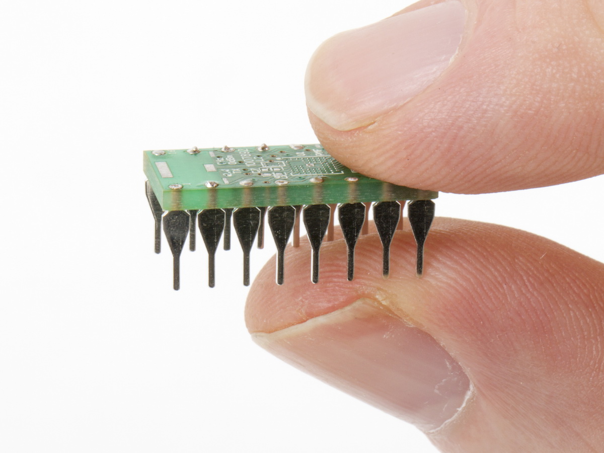 |
Notes
If pins fall out of the Aligner
Flip-Pins are held loosely within the plastic aligner, which is designed to tolerate soldering temperatures. The solder tail extends approximately 0.062” so that when installed in a PCB that is the common thickness of 0.062”, it will result in a near flush top surface. Sometimes the pins can fall out before being soldered into the board. Just re-insert the pin into the plastic aligner, and adjust it to be at the same depth as the rest of the pins.
Using Flip-Pins when you need a non-standard length
If you need to install a row of pins that is not one of the standard lengths (8, 14, and 20 pins), you can use multiple Flip-Pins to get the length you need, or you can remove pins from an aligner, as needed. Because the length of the plastic aligner is 0.020” longer than the number of pins times 0.100” , the Flip-Pins can’t be installed end-to-end. The solution is to solder the pins in two stages. For example, if you were adding pins to a Teensy 3.6 (it needs two rows of 24 pins each), you could use two 20-pin parts and one 8-pin part.
Position the 20-pin Flip-Pin strips so that there are 4 consecutive empty holes at one end on the Teensy. After these 20 pins have been soldered in (on both sides of the Teensy), remove the plastic aligner. Take the 8-pin Flip-Pins strip and remove 4 pins from one end, and place the remaining 4 pins into the empty holes on the Teensy, and the 4 empty positions in the 8 pin plastic aligner over the adjacent 4 pins of the 20-pin strip that you have already installed. This will align the remaining 4 pins with the rest of the row. Solder in the 4 pins. Place the 4 pins you removed from the 8-pin strip back into the plastic aligner, and repeat the soldering process for the other side.
How much solder is enough?
When soldering Flip-Pins, adding too much solder will not be obvious, as the top surface will remain flat or just have a slight dome, while the excess solder will wick down the pin. If this is your first time soldering Flip-Pins, practicing on a spare PCB is an option. Alternatively, you can just solder enough to cover the top of the hole, and then remove the plastic aligner to inspect the other side. If pins do not have enough solder, the aligner can be placed back over the pins and additional solder can be applied.
How to do re-work on Flip-Pins
If a pin needs to be replaced, or if it is not correctly aligned (this should never happen during initial soldering of Flip-Pins, since the plastic aligner holds all the pins in alignment), the plastic aligner can be reused. If you still have some pins soldered in, and they are correctly aligned, they can act as a guide for the pins that are being reworked or replaced. First, remove the miss-aligned pins (or the ones being reworked) and remove the solder from the hole in the PCB (solder sucker or solder wick). Then take one of the plastic aligners (did you keep them after soldering the pins?) and place pins into it just for the positions being reworked, the remaining holes in the aligner are left empty, and match the pins already on the PCB that are not being re-worked. You should then be able to place the aligner with the rework pins back over the pins on the PCB, and everything should be nicely aligned. Then just solder these pins.