
Flip-Pins
IC pins for your own projects.
 Flip-Pins-08
 OSHChip
Description
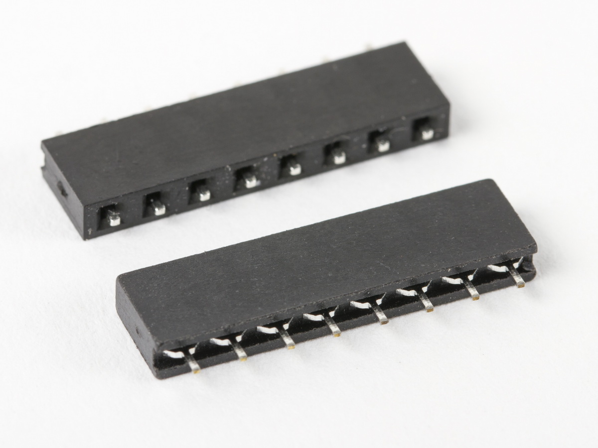
Flip-Pins are the third generation of the Integrated Circuit (IC) pins designed by Fliptronics for use in products like OSHChip. The goal for Flip-Pins was to create pins that could be soldered into a Printed Circuit Board (PCB) and to look as much like an IC pin as possible. (Current production OSHChips use the second generation pins, and will change over to third generation with the next production run.) With the unique plastic aligner, the pins are held 0.100” apart, with a 0.062” solder tail exposed.
A significant feature of Flip-Pins is that their width (0.020”) is the same as traditional Dual-Inline-Package (DIP) IC pins, and so Flip-Pins are directly compatible with standard Breadboards. Many people use header pins which are square to connect their PCBs to breadboards, and are unaware that header pins damage the breadboard because they are wider than standard DIP pins. PCBs that use Flip-Pins are easier to insert and remove from breadboards, compared to PCBs with header pins. Unlike header pins, Flip-Pins are also compatible with IC sockets, see below for examples. This has allowed users to create PCBs that are replacements for existing ICs (because they are no longer available) or even upgrades to previous devices. These PCBs can then be plugged into existing IC sockets in an existing system.
Flip-Pin are available in 3 lengths: 8, 14, and 20 pins. Other lengths can be achieved by either using multiple strips, or removing pins from a strip.
How Flip-Pins are used
When soldered into PCBs that are commonly 0.062” thick, a near flush surface can be achieved on the non-pin side of the PCB (see the OSHChip on a penny picture, above). If you use a thinner PCB (such as .032”), then part of the pin will be above the PCB. After soldering the pins into your PCB, the plastic aligner can be easily removed and discarded.
Detailed description of how to solder Flip-Pins
The recommended footprint on your PCB for Flip-Pins is shown in the datasheet. Briefly, the holes should be 0.025 inches in diameter, and the associated pads should be at least 0.040” in diameter. On the top side of your PCB (the side that does not have the pins) you can place components and vias close to the pads. On the bottom of the PCB, you must leave clearance for the plastic aligner. For the narrow dimension, the clearance should be 0.120” centered on the center line of the row of pins. For the length, the clearance area should be 0.100” times the number of pins +0.040”. For example, for the 14 pin version of Flip- Pins, the clearance area is 0.120” x 1.440”.
Libraries
For your convenience, PCB CAD libraries have already been created for the following CAD systems:
Documents
- Datasheet Flip-Pins-XX_REV_A.pdf
- Step model for a single pin
- Step model for a single pin with aligner
Compatibility
Examples of breadboards that Flip-Pins were designed for:
- EMSL 170 point Breadboard
- EMSL 630 Point Transparent Breadboard
- DigiKey 170 point Breadboard
- DigiKey 830 point Breadboard
- Sparkfun 170 point Breadboard
- Sparkfun 830 point Breadboard
- Adafruit 170 point Breadboard
- Adafruit 830 point Breadboard
Flip-Pins are compatible with IC sockets that have flat contacts, for example:
- EMSL 16 pin DIP sockets
- Digikey 16 pin DIP sockets
- Sparkfun 16 pin DIP sockets
- Adafruit 16 pin DIP sockets
Flip-Pins might not be compatible with IC sockets that have a round entry hole for the IC pin. Please check carefully with an actual socket. For example, these types of sockets: DigiKey ED3016-ND
Examples of Boards that can be used with Flip-Pins
- Printed Circuit Board you design yourself, maybe etching them yourself, or milling, or having them manufactured by a company like OSHPark
- EMSL breakout boards
- Sparkfun breakout boards
- Adafruit breakout boards
Buying Flip-Pins
Flip-Pins are available in 3 different lengths: 8, 14, and 20 pins.
The following are authorized distributors for Flip-Pins:
- OSHChip store on Tindie
- Evil Mad Scientist LLC (8 pin) (14 pin) (20 pin)
- Sparkfun Electronics (8 pin) (14 pin) (20 pin)
- Distributor A (not yet setup)
- Distributor D (not yet setup)